29+ deployment diagram components
This is a Deployment Diagram example. Component diagrams are physical analogs of class diagram.

Library Management System Uml Component Diagram Template Component Diagram Diagram Templates
A deployment diagram in the Unified Modeling Language models the physical deployment of artifacts on nodes.

. What are the parts of a deployment diagram. Following are the purposes of deployment diagram. The very first item is the node it is one of the most important parts of the entire system.
The deployment diagram does not focus on the logical components of the system but it put its attention on the hardware topology. Essentially every component of a deployment diagram is a node. Deployment Diagrams A deployment diagram is a diagram that shows the configuration of run time processing nodes.
A component is a code module. View 29-Deployment Diagrams-29-Apr-2021Material_I_29-Apr-2021_deployment_diagrampdf from ITE 1007 at Vellore Institute of Technology. The configuration of hardware is represented by attributes of nodes.
View 29-Deployment Diagrams-29-Apr-2021Material_I_29-Apr-2021_deployment_diagrampdf from ITE 1007 at Vellore Institute of Technology. Deployment diagrams are used by the. Everything else is simply.
Deployment diagrams show the physical configurations. To describe a web site for example a deployment diagram would show. Deployment diagrams show the relationships between the software and hardware components in the system and the.
A UML deployment diagram depicts a static view of the run-time configuration of hardware nodes and the software components that run on those nodes. In UML deployment diagrams model the physical architecture of a system. To construct Component Diagram and Deployment Diagram to depict the structural view of the E-library Management.
Instance specification was extended in UML 20 to allow instance of a node to be deployment target in a deployment relationship. Most of the UML diagrams are used to handle logical components but deployment diagrams are made to focus on the hardware topology of a system. Saquib Sheikh Roll No.
Property was also extended in UML 20 with the capability. A node represents any hardware component.

Free Editable Book Club App Uml Deployment Diagram Edrawmax Activity Diagram Diagram Time Diagram

Uml Component Diagram Component Diagram Diagram Data Science

Uml Component Diagram Component Diagram Diagram Diagram Design

Uml Deployment Diagram Diagram Deployment Component Diagram

Component Diagram
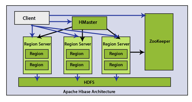
Hbase Architecture A Quick Glance Of Hbase Architecture
Component Diagram Tutorial Complete Guide With Examples Component Diagram Diagram Tutorial

Online Shopping Component Diagram Example Component Diagram Diagram Templates

Product Uml Component Diagram Component Diagram Diagram Templates
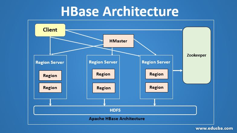
Hbase Architecture A Quick Glance Of Hbase Architecture

Free Editable Online Store Process Uml Component Diagram Edrawmax Component Diagram Time Diagram Diagram

Uml Diagram Types Learn About All 14 Types Of Uml Diagrams Deployment Component Diagram Class Diagram

E Commerce Microservices Uml Deployment Diagram Software Ideas Modeler Application Architecture Diagram Web Application Architecture Deployment

Uml Deployment Diagram Component Diagram Deployment Order Management System

Uml Deployment Diagram Overview Diagram Deployment Tutorial

Uml Deployment Diagram For Online Shopping Diagram Deployment Templates

Uml Diagram Diagram Deployment Component Diagram